Accumulator Applications in Fluid Power Systems
Principal Applications
Hydraulic accumulators have a number of applications in a hydraulic system. These are, primarily:
Auxiliary Power Source
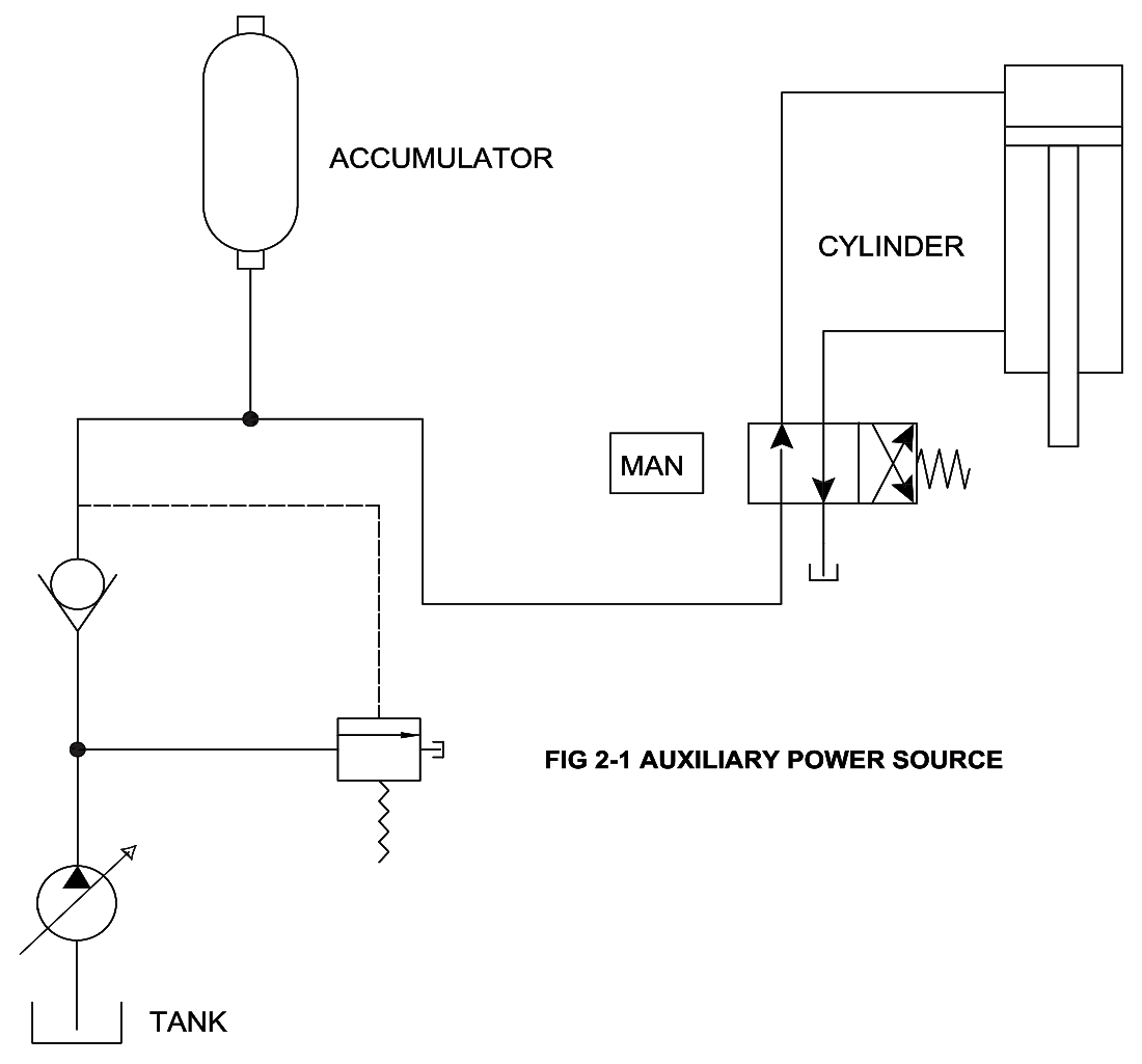
The most common application of hydraulic accumulators is an auxiliary power source. In this application, the accumulator stores the hydraulic fluid delivered by the pump during a portion of the work cycle; then, releases this stored fluid upon demand to complete the cycle, thereby functioning as a secondary source of power and assisting the pump.
In a hydraulic system where intermittent operations are being performed, the use of an accumulator will reduce the size of the hydraulic power unit. In this application ( Figure 2-1) a four- way, two-position, manually operated valve is employed in conjunction with the accumulator. When the handle of the four-way valve is shifted, the oil flows from the accumulator to the blind end of the cylinder. The piston advances until it reaches the end of the stroke. While the desired operation is taking place (for example, curing, casting, pressing), the accumulator is being charged by the pump. The four-way valve is then shifted for the return stroke of the cylinder. Oil from the accumulator and from the pump flows rapidly to the rod end of the cylinder retracting the piston to its initial position.
The accumulator size is selected to supply adequate oil capacity for at least one cycle and is recharged between cycles.
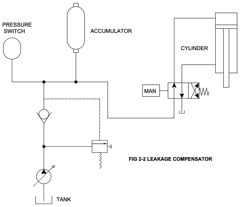
Leakage Compensator
Another application for an accumulator is as a compensator for internal or external leakage during aprolong period when the system is pressurized but not in operation. Figure2-2 shows a hydraulic circuit employing an accumulator as a leakage compensator.
The pump charges the accumulator and the system until the maximum pressure setting on the pressure switch is obtained; contacts on the pressure switch then open, stopping the motor and the pump automatically. The system may be pressurized for a long period of time before leakage replacement oil is drained from the accumulator to drop the system pressure to the allowable minimum pressure setting of the pressure switch. The pressure switch closes the electrical circuit of the pump motor, starting the power unit until recharging of the system is complete.
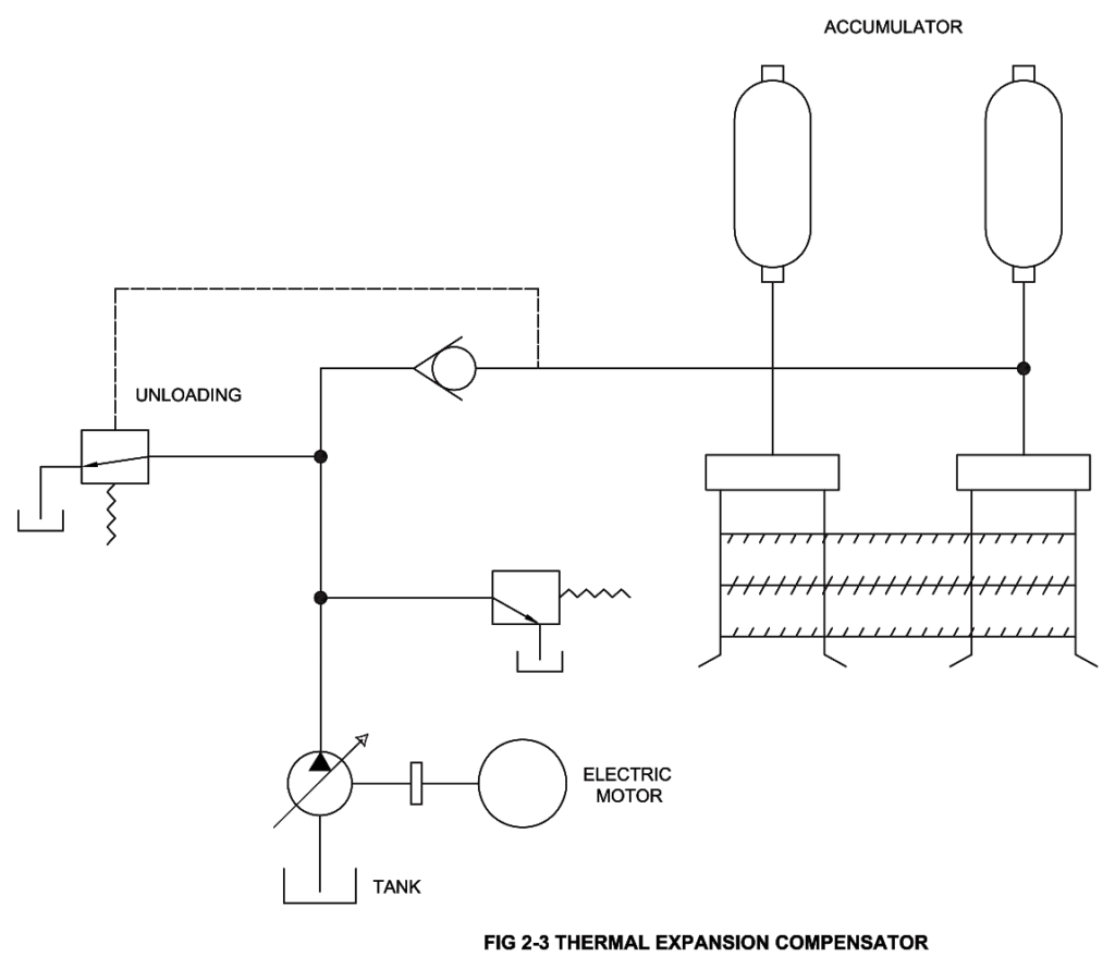
Thermal Expansion Compensator
When closed loop hydraulic systems are subjected to heat conditions, both the pipe lines and the hydraulic fluid expand voIumetricaIIy. And, since the coefficient of cubical expansion of most liquids is higher than that for pipe materials, this expanded liquid volume increases the entire system pressure.
This condition may cause pressure to exceed the limits of safety — or inflict damage on delicate and expensive system components. Under these conditions, the installation of an accumulator of proper capacity, precharged to the normal system working pressure, takes up any increase in the system fluid volume, thus reducing the system pressure to its safe limits. The accumulator also feeds the required fluid volume back into the system as thermal contraction takes place.
Emergency Power Source
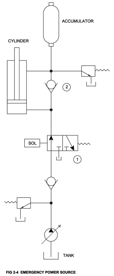
In some hydraulic systems it is necessary for safety reasons to retract the rams of certain cylinders to the starting positions, should the normal supply of oil pressure to the cylinder be interrupted by pump or electrical power failure. Such applications require the use of an accumulator of proper capacity as an emergency power source. A simple circuit in which an accumulator is used for emergency operation is shown in Figure 2-4.
In this circuit, a solenoid operated, two position, three way valve
(1) is employed in conjunction with the accumulator. In the cylinder, the cross section area of the piston rod is one half that of the cylinder tube. When the solenoid valve (1) is energizes, it unseats the check valve (2) and directs the oil under pressure into the
accumulator and rod end of the cylinder. The accumulator charges as the piston of the cylinder advances. If the hydraulic pump fails because of an electrical power failure, the solenoid valve will de-energize, shifting the valve (1) to its original position. The oil stored under pressure then is forced from the accumulator to the end of the cylinder, retracting the piston to the starting position.
Fluid Make-Up Device
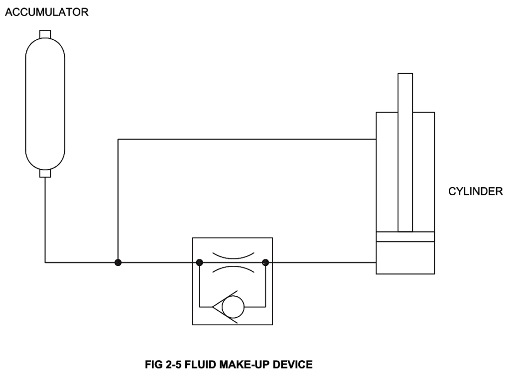
In a closed hydraulic system, an accumulator can be used effectively as a fluid make up device. The accumulator makes up the difference in fluid volume between the rod and the blind end of the hydraulic cylinder. Such a system is illustrated in Figure 2-5. When the piston rod of the cylinder is driven in by high external force, oil is forced from the back side of the piston through the orifice valve to the rod end of the cylinder.
The orifice valve is employed to slow down the movement of the rod, preventing shock at the end of the stroke. Since the volume of oil in the blind end of the cylinder is greater than that of the rod, and due to difference in volume resulting from the space occupied by the piston rod, there is a quantity of excess oil which must be stored somewhere. The accumulator provides a satisfactory solution. The excess oil flows into the accumulator, building up the pressure. When the external load is removed from the piston rod, the accumulator releases its stored energy to extend the piston rod. Again, the accumulator, by discharging into the system, makes up for the greater space in the blind end of the cylinder.
Pulsation Dampener / Hydraulic Shock Absorber
One of the major industrial applications of accumulators is the elimination or reduction of high pressure pulsations or hydraulic line shock
Hydraulic shock or water hammer is usually caused by the sudden stoppage or deceleration of a fluid flowing at high velocity in a pipe line. The hydraulic line shock generates a compression wave at the source (a rapidly closed valve) which travels at the speed of sound up stream to the end of the pipe and back again causing an increase in the line pressure. This wave travels back and forth over the entire length of the pipe line until it is finally dissipated by friction.
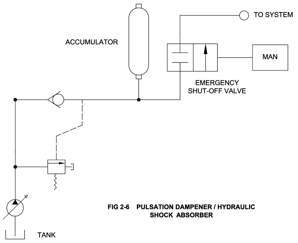
The rapid pressure or high pressure pulsation or surges produced in the system may cause pump line failure, breaks in the lines, external leakage and severe damages to valves and instruments. By installing an accumulator in the line next to the rapidly closing valve (source of shock), shock can be suppressed. Figure 2-6 shows a circuit incorporating an accumulator as a shock suppressing device.
Power Source in Dual Pressure Circuits
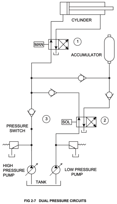
Figure 2-7 illustrates the use of an accumulator in a dual pressure circuit for a hydraulic press. In such an application, an accumulator provides increased oil capacity for higher piston speed during the non-working portion of the cycle. This reduces the total cycle time and power requirements. This system is equipped with a large volume, low pressure pump and a small volume, high pressure pump.
When the handle of the four-way valve (1) is shifted to advance the piston of the press cylinder, the delivery of both pumps, as well as the oil stored in the accumulator, discharges into the blind end of the press cylinder and the piston rod moves down rapidly at low pressure. When the ram meets the work piece, the system pressure immediately builds up, closing the pressure switch (3). This, in turn, energizes the solenoid operated valve (2), so that the delivery from the large volume pump is deflected towards the accumulator to recharge. The small volume high pressure pump continues to supply high pressure oil to the cylinder for press operation. When the handle of the four way valve (1) is shifted to its original position, both pump deliveries and the accumulator discharge are again available. When fully retracted, the pressure switch (3), is again closed, energizing the valve solenoid (2). This action actuate the valve, directing the delivery of the large volume pump to recharge the accumulator. At the same time, the delivery of the high pressure pump is utilized to hold the ram up. One relief valve is required on each pump line.
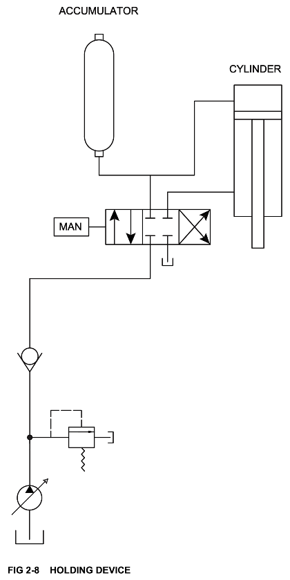
Holding Device
In a hydraulic system where it is necessary to maintain high pressure in a cylinder for long periods of time, an accumulator can be used very effectively. It will also eliminate pressure variations created by varying demands of different branches of the system.
In Figure 2-8, when the handle of the three position four-way valve is shifted, directing the oil flow towards the blind end of the press cylinder, the piston advances rapidly. When the ram meets the work piece, the pressure builds up in the accumulator. Next, the operator shifts the valve handle to the neutral position. This locks the fluid in the accumulator and in the cylinder under high pressure. Oil being delivered by the pump is directed to the reservoir under very low pressure. This reduces the wear on the motor and the pump. It also minimizes the possibility of the oil overheating, since operation of the pump against the relief valve for any prolonged period has been eliminated. When the pressing operation has been completed, the operator shifts the valve handle into the reverse. This causes the ram to retract and the accumulator discharges. The work cycle is then completed and the operator returns the handle of the four-way valve to the neutral position.
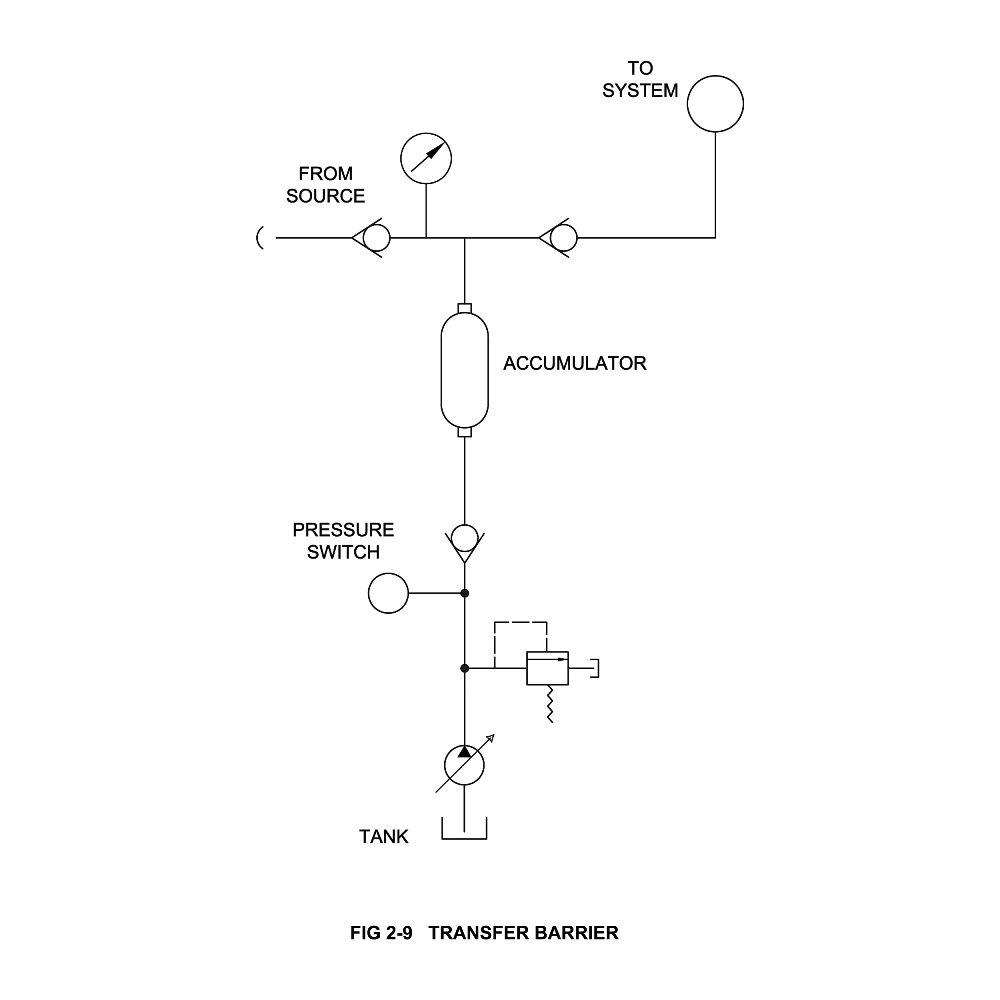
Transfer Barrier
In a system where, fluid pressure developed on one side of the circuit must be transferred, as developed, to another fluid without any possibility of the two fluids intermixing, the bladder type accumulator provides the satisfactory solution (Figure 2-9). The accumulator bladder acts as a flexible barrier between the fluids or between agas and a fluid providing instantaneous response without reducing the system pressure. The barrier must, however, be of a material that will not be affected by the system fluid. One example of this is a system in which a pressure vessel or instrument has to be proof pressure tested with a special non-flammable hydraulic fluid, but the hydraulic test equipment used may not be capable of handling the fluid. The transfer barrier accumulator is designed to meet such a requirement.
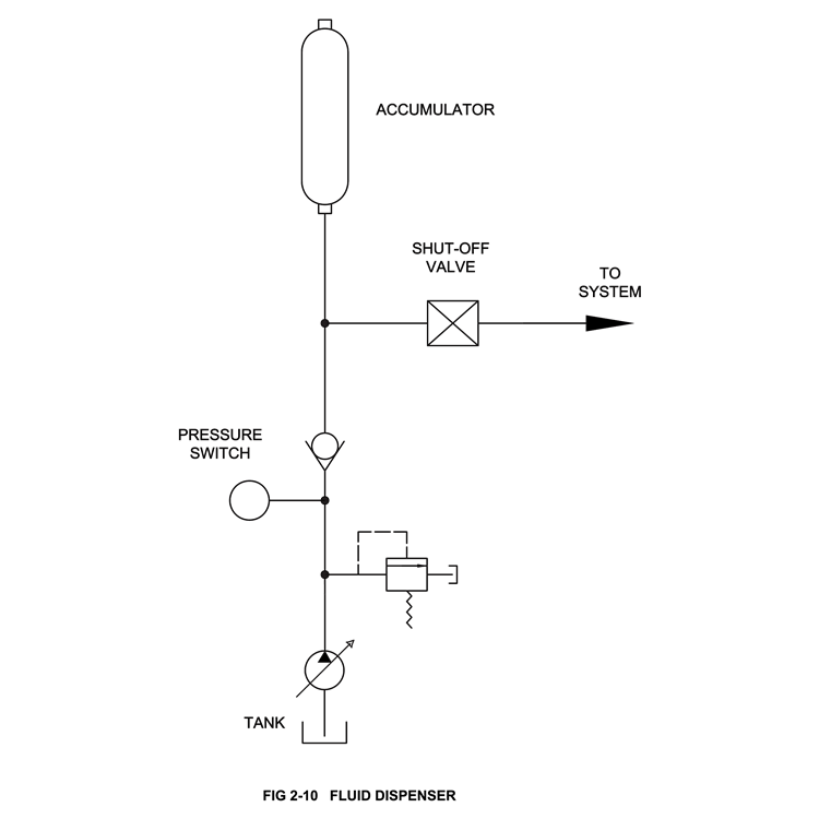
Fluid Dispenser
Figure 2-10 shows a circuit in which an accumulator is being used as a fluid or lubricant dispenser.
Liquids and Lubricants can be stored in an accumulator to be dispensed to a number of bearings of acomplicated machine as and when needed under controlled pressure. In system where constant, but extremely slow rates of lubrication are desired, an accumulator can provide a constant, controlled supply of lubricant for a long period of time before any recharging is required.